Feeds:
Posts
Comments

Archive for the ‘DIY’ Category

Another custom order, it’s the venerable Commodore PET professional computer – you know it’s a pro because it had 32kB of memory (in 1979, that was quite a bit, you pesky kids).

This is the 2001N model – the first to have a real keyboard and boosted RAM (up from 8KB in the original 2001 model). Available in the Rabbit Engineering online store.

Read Full Post »

10 months after the prototype was completed, and three concentrated months of product development, the Model G1 is now available to order. We’ve sold two already!

It’s quite a lot of work taking a prototype to a state where you can sell it – improving the design for better manufacturability, deciding what needs to go into the manual, deciding on packaging, setting the price, marketing – it’s an exhausting list. And I’m sure that lots of interesting hiccups are still waiting around the corner 🙂 Click here to go to the details page, and order one if you like!

Read Full Post »

After about 500 hours of printing reliably, my Makerbot Replicator 2 finally barfed. I walked in to a 4 hour print completion that looked like this:

Woah. When you walk in on a print failure like this, it’s important to root-cause the problem, so that you can prevent it in future. Not only did I lose about 4 hours on this job, but also about $5 in PLA. I looked over the printer first to check for the usual problems – extruder head movement restricted, PLA feed issues. Nothing there, so I took a closer look at the piece. I noticed an interesting pattern:

Notice how the problem started at a certain layer – that is not really interesting; notice instead how the layers above the break point are basically intact, just shifted over to the left (along the X axis). A couple of possibilities:

  1. A problem with the SD card or the X3G file on the SD.
  2. Corrupted firmware (on how it controls the X axis)
  3. Problems on the X axis travel (bad lubrication, loose drive belt)

First I took a look at 1 and 2 – the software problems. I looked at those first because those are the simplest to fix. I reformatted the SD card, re-built the X3G file and reset the printer to factory defaults. Then I kicked off the same print job and noticed the problem in action (thankfully it was very easy to reproduce). Here is a video of the issue:

Hear the THUNK THUNK? That is the head either stopping without deceleration, or step skipping. This is what happens on the print:

The squiggly line is where the steps are skipped. This means that you loose alignment between layers. You can see it more clearly in this larger photo:

So this makes the printer basically useless. Bummer. I started digging around and found a great YouTube video by forbinone that describes the same problem and gives a very simple fix. Basically, the problem is that the X-axis servo cable, from being too tightly crimped in the factory, and the thousands of forwards-backwards cycles, causes some of the cores inside the cable to break. That means skipped steps. The solution of course is to replace the cable.

Once you remove the right-side MDF from the Replicator 2, you can see the problem in the X-axis stepper cable (light grey ribbon cable) – it is crimped far too tightly.

Mark the point where the kink in the cable forms (in the diagram above, the problem space is at the blue mark on the cable near the top-right of the picture), and then remove the little bar holding the cable in place to free the grey cable. Ensure the black ribbon remains in place (it is for the homing switch and does not suffer this problem), and replace the little bar.

Now you just trim away the problem section of cable, and splice in some new ribbon cable. To ensure the splicing did not lead to any shorts across the four wires, I decided to use some 0.1″ headers.

Then add in the new section. Be sure to add enough that there is no tension in the wire – there should be enough play to allow the X-axis gantry it to move smoothly forwards and backwards without getting tangled anywhere. It is critical to ensure you keep the polarity correct – that is, don’t accidentally flip the splice so that the leftmost cable on one end of the original ribbon is now connected to the rightmost cable of the ribbon. That could badly damage the printer.

To ensure the new longer section did not get tangled into the rest of the machine, I cable tied it to the front-right vertical beam.

To finish up, I added some insulation to the joints, and bolted the MDF back to the machine.

It definitely looks a little war weary, but after the operation, it runs perfectly. I did the same 4 hour part again, and it came out without any issues:

Read Full Post »

This story begins with a simple email about rotary encoders, and ends with me shipping my first paid commission.

It’s a big personal milestone, but really not as a big a deal as you might think in terms of just getting it done. The device I designed and delivered was the Rabbit Engineering Model I1, an interface module that lets flight sim cockpit builders (like my customer), home arcade cabinet builders, and anyone who wants to build a custom controller to connect a variety of buttons, switches, potentiometers, and rotary encoders to their computer by USB. You can get an overview on the product page, and order one for yourself.

By the way, if you get the chance to make a project for someone who has a real problem that you can solve for them, I strongly recommend you do it – this has easily been the most satisfying spare-time project I have worked on.

In early August, I got an email from Mr. G (he has a real name, but let’s keep it anonymous) asking about the rotary switches I used in my custom SF2 controller. He asked simply if I knew of a place that sold them cheaply. After  a couple of mails, I suggested he use rotary encoders together with a microcontroller like the TeensyUSB. Alas, Mr. G did not have the skills to pull that off. So I thought, hey, why not help a fellow flight simmer out and build it for him? I offered to do it for the cost of parts plus a small markup. He accepted. We had a commissioned job!

I had already had experience on similar projects and experiments such as the FSX MCP panel, the iPac distribution box, the SF2 controller, the Arduino Leonardo keyboard experiments, and the Multijoy_retro; so I was confident I could pull it off in a month or so.

When doing any kind of engineering project it’s important to set a clear spec (specification) by working with the customer – so we had a long exchange about exactly what the machine would do, I offered some options (with the relative costs), and Mr G. settled on what solved his problem and fit his budget. A simple agreement email locked us both in (I would deliver by end of August, and he would pay the agreed amount), and the three week clock began to tick down.


Essentially, it would be an interface device that would have as many as 42 buttons, switches, rotary encoders or potentiometers connected and converted to key presses, joystick buttons and/or joystick axis events. It would connect to the host by USB without drivers, and the configuration would be programmable by a config file on an SD card. Here is the final spec we agreed upon.

  • 42 configurable inputs, all can be used as binary IO, each using one of two modes:
    Push-Hold – the event occurs as long as the button is held down (for push buttons).
    Push-Nohold – the event occurs only once, regardless of push duration (for single events coming out of toggle switches)
  • All can be used to sense 21 rotary encoders (2 inputs needed per rotary). Clockwise rotation sends one event, Counterclockwise rotation sends a different event
  • 6 can be configured as analog inputs, sensing a 10K potentiometer (linear or logarithmic).
  • Inputs can generate any of the following events:
    Key press/release – single key, or with one modifier key (shift, ctrl, alt)
    Joystick button press (one of 32 buttons)
    Analog inputs can be mapped to one of 6 joystick axes
  • Configuration of the inputs is done by modifying a text file in an SD card which is read when the device is plugged into the USB port.

I really tried to convince him on an option to have expansion cards that would add more inputs using shift registers, because it was a feature I wanted to work on; but it broke his budget. In the end, you build for the customer and not yourself, so his decision stood.

Now the design phase – I had already played around with rotary encoders and the TeensyUSB, but only using interrupts. To satisfy the spec I would need more than the handful of interrupts that the Teensy provides, so I began to experiment with polling modes. This was kind of a risky/dumb move on my part, because if I failed to figure it out I would have had to break the spec/cancel the project/upset the customer, but believe me, that fact was very motivating. After a couple of evenings slaving over a hot C++ compiler, I got that working; turn clockwise and you get one input set, turn counterclockwise and get another, with minimal side effects (turn the rotary too fast and you miss steps, which is a bug the Saitek Pro Flight Multi Panel also has!). The other interesting feature, PushNoHold (holding down a button triggers only one input event) was easily done using the standard Arduino Bounce library.


The next “interesting” part in terms of code was SD card reading, which really should not have been hard, but gave quite a few hassles. Ultimately it was all related to the type of SD card – I needed to use an SDHC type rather than the SD types I was assuming I could use. Remember kids, try different disk formats if you’re having disk reading issues.

The big technology choice for this project was the microprocessor to use. I am a big fan of the TeensyUSB line, and I already have experience with it, so I knew it would be the one. I chose the Teensy 2++ in the end because of its large number of input pins and RAM; To satisfy the configurability requirement in the spec, I would need storage per input and 2KB would not be enough.


One painful (hardware) bug I hit was around pin 6 on the Teensy 2++. This is connected to the LED, and so behaves differently from the other pins. In order to turn this into a normal input, I had to add a pull-down resistor, and have the input  connect to 5+ rather than to ground like the other pins. Rather than try to reconfigure a big part of the project, I decided to document the strange behavior in the manual (a trick I learned from Clive Sinclair and his scientific calculator).

Writing the code was fairly straightforward, but my days as a C# programmer have left me soft and flabby in terms of pointer handling, so I got slapped around a bit by C++. One fine evening, at about 5am, I finally got all the code running and tested. This project actually has the most code of any I have done (mostly around the config file parsing).

Time to move onto the physical design. There were two aspects to this: Provide an interface to the input pins, ground plane, and +5 supply (needed for potentiometers) in a way that would make for simple integration of the Model I1 into the electronics of the customer’s project; and then a protective shell and means to physically attach it into the customer’s project (by gluing, bolting, or whatever).

The interface was the most important part – I decided to simplify things by having three clusters of connectors: The input pins (two long headers), a ground plane (a pair of headers with way too many pins), and a power rail with +5 and ground right next to each other. This makes adding input devices simple – just add some male 0.1″ headers and away you go.


And here it is in the shell. The tolerances were tighter than in previous projects, because I wanted to be as compact as possible (the bigger this device, the bigger the customer’s enclosure would have to be). Why yes, that is our old friend hot glue there.


The manual (more on that below) explains how to wire and connect each type of input device (potentiometer, button, etc). I used color coding on the headers to ensure that connecting was as error-free as possible.

Here it is painted (the white numbers are not on the device – this is actually a screen grab from the manual):

Then came the testing. Testing is not my favorite part of any build, but on this project which would be going out into the wide world and would be hard to fix once deployed, I took some extra time and built a little test rig with the various types of input devices attached. Well, “test rig” is a kind term, it’s a chunk of MDF with some holes. Still, it did the job OK.

Then I tested every type of input on every pin. Good times. Grudgingly, I admit it was worth it because I found two software bugs and one short circuit.

The plastic shell was designed in OpenSCAD and 3D printed. As usual, it began with a sketch (which I made in Las Vegas while there for Black Hat 2014/Defcon 22 – always carry a sketch book with you!).

I wanted to give it a designed look, but at the same time this would live inside a beige box one day, so spending too much time was not necessary. It is essentially a flat box with mounting holes, but I used hex bolts instead of screws to give it a little interest.

Then the printing (I think total print time was around three hours):

And presto! We have a shell:


I embossed the Rabbit logo on the back, as there was a huge expanse of plastic.

I also printed a matching shell for the SD card disk drive.

For physically mounting the Model I1 to a project, there are two options – you can bolt it in using the bolt holes in the shell, or you can screw in the provided “gluing feet” – you then glue the feet to your project. The idea is that you don’t want to glue the device itself to your project, because if you need to move/remove, the force could damage it. So instead you can just unscrew the device from its feet, and then grunt and pull at the feet all you need without risking the delicate electronics (a trick I developed for the Multijoy_retro).

Then came the writing – this beast would need a detailed manual, because I had to document not only how to connect input devices, but also the file format for the configuration file (which is fairly complex due to all the options you can have). If you thought testing was bad, then writing is the worst, but a well documented product really makes a huge difference – not only does it give an impression of quality and thoroughness, but it saves you a lot of time and energy from all the customer questions/emails you have avoided.

Once all that was done, it was time for the finishing touch – update the Rabbit Engineering site with the product information, and then build a nice packaging experience. When you are building for a paying customer, their experience of their product starts from the very moment they open the box, so that deserves some design and attention also. Sadly, there is no cardboard 3D printer, so a lot of Xacto and sticky tape action followed.

The manual goes on top. This is essentially the first contact the customer has with the device they just bought, so you want to create a “Woah, cool!” reaction.

Then , when they remove the manual, they see all the parts neatly laid out in the box.

Pack all that into into a shipping box, and off it goes to its new home in the wilds of North Carolina. Apparently it’s wild there, I’ve never been, so I will take their word for it.

In the end I was able to get the project done just three days short of the promised date. From conception to shipping was just over 20 days – this was possible mostly because I had already solved all of the underlying problems before I began. If you need a Model I1 for your own project, you can order one up from our online store.

Read Full Post »

A larger project I want to complete as a RabbitEngineering.com milestone is a standalone computer, in 1980s style – complete with external storage, controller and screen. Top priority for this project is innovative and appealing design. I decided to begin with the controller (mouse replacement).

I decided to not use a mouse or trackball – those are not innovative enough; instead, I decided to model my controller on a well-established interface that is not used in computing, but popular in some areas of aviation – the HOTAS throttle. This is an example, from the McDonnell Douglas F-15 fighter:

The throttle is used to control the thrust of the engines by moving it forwards and backwards, but in the 1960s cockpit designers, realizing that a pilot’s hand needed to rest on the throttle for most of a flight, began to add controls for common functions – RADAR settings, the air brake, radio selectors, etc. This was done by adding first buttons to the throttle, and later 4 and even 5 way digital joysticks, in places where the fingers rested naturally.

I decided to use the throttle as the basis of my design. I wanted to keep the physical design minimalist and geometric, so I first settled on a simple cylinder with a flattened base. I 3D printed out test form in white PLA, and marked with sharpies where my fingers rested (this is a good technique for noting required adjustments to 3D printed parts).

Immediately a problem became apparent – the top part, where the fingers curl around the form, was too wide, leading the hand to be overextended and uncomfortable. Back to OpenSCAD. The tube was at least not wasted – I now use it as a pencil holder on my workbench.

For the next form, I narrowed the top, but kept the base wide for stability – in essence, the new form is a triangular prism with spheres for vertices. Again, I printed in white PLA and marked where the fingers naturally lay using sharpies.

Front view:

Left view (where the thumb rests, and the control for the mouse cursor will be):

Right view:

Once that was done, it was time to measure the locations of all the buttons and transfer them into OpenSCAD to begin modelling the complete shape. The final controller would have the following electronic components:

  • A two-axis analog joystick to control the cursor (for compactness, I used the part used in the Nintendo PSP, which is available at Adafruit). Controlled by the thumb.
  • A 5-way digital joystick for left click (depress the joystick), mouse wheel up and down, and scroll page left and right (also from Adafruit). Controlled by the index finger.
  • 6mm tact switch for middle click. Controlled by the middle finger (from Adafruit)
  • 6mm tact switch for right click. Controller by the ring finger (from Adafruit)
  • A TeensyUSB 2.0 programmed as a USB keyboard and mouse as the HID interface. The teensy can be programmed with Arduino libraries, but is much more compact and has better USB device emulation (you can also get these from Adafruit).

A new technique I wanted to try on this project was to have plywood inlays in plastic parts. On the Nespoise I had mixed black PLA and plywood to a very nice effect, but I wanted to try and hide the edge of the plywood this time. Because OpenSCAD lets me export to STL which is consumed by both Makerware (for printing PLA) and CamBam (for CnC cutting), I thought it would be fairly straightforward to do. Here is the shell from the outside (minus buttons):

The shell consists of an upper and a lower half, joined by two #6 imperial screws. The top half is the complex part, with the buttons/joystick openings, screw posts, and hinges:

Internally it’s more compact that any other project I’ve worked on – to ensure all the parts deconflict correctly, I rendered a number of strange cross sections (OpenSCAD makes this very easy). Here are some of the more interesting ones:

I had never worked with hinges and only had limited experience with moving parts like d-pads, so I decided to make test prints of just these areas. Turned out this was a good idea, as the tight tolerances I originally put in caused annoying sticking of the parts.


 Once all the bugs in the top half were resolved, it was time to print the complete shell. This required the use of supports which I don’t often use, and I ended up with some untidy/incomplete areas in the print (for example, one screw post only printed halfway before breaking down). Given it was a 5 hour print, I decided I could live with the bugs, especially given they were all inside the body (the external surface was smooth). I then glued/screwed the switches and joysticks in, and got ready to wire them in place.

I then spent some time programming the firmware for the Teensy. It’s better to do the bulk of this before final assembly, because you might discover short circuits, bad switches, or other hardware related bugs during programming, and you want to avoid having to disassemble the project to resolve those.

Here are all the plastic parts (with most of the electronics) ready to test.

I then cut the plywood inlays and they snapped nicely into place, and I added a little superglue to ensure they stayed in place. Time to add the remaining electronics before further testing. Here are some views of the top half ready to close – it is a tight fit.

Here are all the parts labelled. For the power light, I used the “natural PLA lens with logo bezel” trick I invented for the NESPo and used in the NESPoise, this time with the Rabbit Engineering logo.

On the bottom half I added two 1 Oz fishing weights, to make the controller feel more solid on the table. I wanted to avoid users from mistakenly moving it around as they would a mouse. The extra weight plus rubber non-slip feet makes it adhere to the table surface nicely.

Time for final assembly – here it is next to the second form:

Now to test it for usability. I found the cursor speed needed some tweaking, so I made some changes to the firmware. Teensy makes this a simple and painless process.

Here are some views of the completed controller, showing the power light illuminated:

Here it is in use, to give an idea of how the hand fits:

You can grab all the files to make your own at Thingiverse.


Read Full Post »

When the Xbox team launched the Xbox One, they all got a special edition of the Xbox One which was white and stated “I MADE THIS”. Here’s your chance to say you also made an Xbox One! And you won’t have to fork out $3000 on EBay either.

Download the files to print your own from Thingiverse.


Read Full Post »

I recently picked up an Atari 1200XL from a guy at work, and got into the mood to return to new mini machines. Instead of the 1200XL (which was a bit of a bomb), I decided to do the far more popular 800XL. And of course you need some media, so I did the Atari 1050 disk drive also.

As usual, you can pick up the files to print your own at Thingiverse.


Read Full Post »

20 Mini NES for SRGE

I’ve been working on a great early registration incentive for the Seattle Retro Gaming Expo (SRGE2014). Folks who register early stand a chance to win one of 20 mini NES machines. I’ve never mass produced any of the minis (the most I did was two each of the Xbox One and C-64), so it was bound to be a new experience.

It was a slog – people often ask if I sell my minis, and this experience did not make me want to start. Well, it did a little I guess. But it took a very long time to make just 20 of these. Here are some photos of the journey.

And so we begin printing…

At one point I ran out of white PLA. There was this much left on the spool after ending a five hour print. If I had run out before finishing the print, all those hours would have been wasted. Phew!

And then the spraying. One advantage of this project is that I got lots of spraying practice – I’m pretty good at that now. But my lungs are probably the colour of retro computer plastic by now.

Each mini NES has 9 parts, so the batch of 20 needed printing close to 200 pieces. Here are a batch of parts sprayed and ready to assemble:

Gluing together some controllers. Doing the buttons (not pictured here) took a lot of tweezer work.

Gluing and clamping…

Here is a little pile of them…

And then THE WALL OF NES.

Or the GREAT PYRAMID OF NESSOS

Once all done, they are ready to bag. I decided to put a little insert into the bag with the SRGE logo and some info on the machine.

Here is a baggie, ready to go.

And here are the baggies, ready to go!

And on April 30 we will pull the winners from our virtual hat! If you’d like a chance to win one of these, register for a weekend pass for SRGE2014 before April 30!


Read Full Post »

UPDATE (9/1/2014): If you are looking to build a project like this, see my post on the Rabbit Engineering Model I1 device.

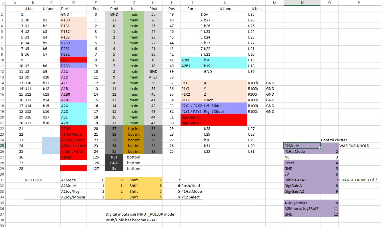
#1stworldproblems – I have a lot of very old joysticks. Too many? No, don’t be silly, no such thing. This hoarding habit is related to my collection of 80s and 90s flight sim paraphernalia in general.

It’s not too bad owning a lot of old flight sim software, because you can just crank up an emulator like DosBox or VICE and enjoy your clunky old untextured polygons. But using your retro flight sim hardware is not quite so easy. You can get an adaptor that allows you to use even the more complex joysticks such as the Thrustmaster FCS, but they have two problems: (1) They only convert PC 15 pin joysticks, and not the Atari/Commodore 9 pin digital sticks and (2) where’s the fun in that? Anyway, what I really wanted was a converter that:

  1. Accepted 9 pin and 15 pin joysticks, including those using the CH Flightstick Pro and Thrustmaster FCS hat switch standards
  2. Accepted two retro joystick simultaneously to allow for joystick/throttle/rudder combos
  3. Converted an analog 15 pin joystick into digital output (for use with emulated 8 bit games)
  4. Converted a digital 9 pin joystick into analog USB joystick (for using digital joysticks with PC sims)
  5. Converted a digital 9 pin joystick into USB mouse input
  6. Accepted arbitrary switches and converted them into joystick buttons for creating new custom input devices (like my previous Strike Fighters 2 radar/armament panel project)

That’s a tall order – this will need to be a microprocessor based project (my first). My first instinct was to use the Arduino Leonardo, which I really like and already have some experience with, but a couple of things put me off – it’s light on memory (2.5k), which limits growth potential for code; it has few digital inputs (20) and although it can be HID-configured as a joystick, it’s not trivial to make it be simultaneously a HID joystick, mouse and keyboard. Plus, it’s physically pretty big. Instead, I went with the Teensy++ 2.0, which uses the AT90USB1286, an 8 bit AVR running at 16MHz. It has 128k of flash, 8k of RAM, 40 digital inputs, 8 analog inputs, and more importantly, it can be easily configured as a Joystick (6 axis, 32 buttons), keyboard and mouse on the same HID device. It’s the size of two postage stamps, and costs $24. And it’s manufactured in the garage of an adorable Portland couple. Perfect.

First thing was to work out the electronics and firmware. For the two analog devices (15 pin joysticks), I would accept one as a full flight stick (i.e. 3 axis plus hat switch plus 4 buttons), and the other would be two axes and four buttons (I only have six output axes after all) – this one would be used as a throttle and/or rudder pedals. This step was fairly easy – get the pinout for a PC joystick, and then remember that PC joysticks use their potentiometers as voltage dividers – this means you need to add a 100kΩ resistor between the Teensy pin and ground:

This is required for each axis. The buttons are a simple case of connecting the Teensy’s digital pin to ground. The hat switches are a bit more complex, because CH Products and Thrustmaster came up with quite different ways of implementing those – more on that in this post. Now for the digital devices (9 pin joysticks), which are very simple – the joystick just connects the input to ground. I decided to expand slightly from the Atari standard by allowing two buttons (like the Commodore Amiga used). Here is the pinout. I also added a 37 pin input to expose all 32 buttons for a custom devices – it surfaces one pin per button, plus one for +5v and one for ground.

Those are the device inputs. In order to implement the various modes for the device, I also needed to add some support inputs:

  1. For each digital device input, a ‘gain’ potentiometer to scale the amount of output on the mouse/joystick.
  2. Because the digital and analog devices share joystick axis outputs, a switch to inhibit the digital devices (otherwise you get interference between them)
  3. A switch to select joystick/keyboard mode output on digital device 1
  4. A switch to select joystick/mouse mode output in digital device 2
  5. A switch to select if analog device 1 uses Thrustmaster FCS or Flightstick Pro hat switch
  6. A switch to select if analog device 2 outputs keyboard or joystick signals
  7. A reset button (needed to reprogram the Teensy).

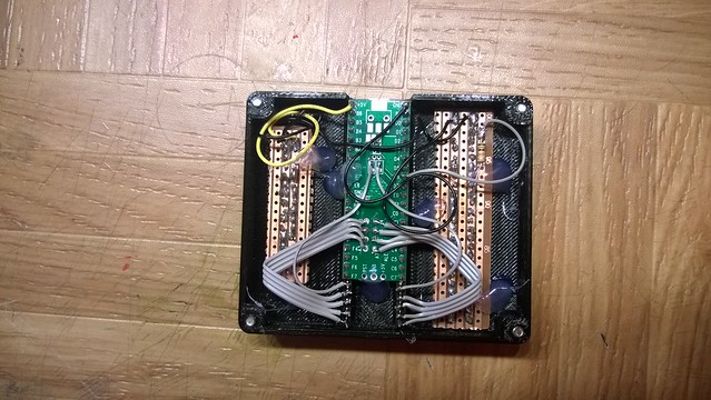
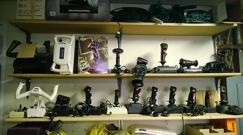
I also decided to add LEDs to indicate the whole box was live (plugged in), and another to show if the digital devices were inhibited. When you lay all that over the Teensy’s pins, this is what you get:

Note that not all the Teensy’s pins are surfaced on its two side edges – some are in the center of the board. Once all that was locked, I soldered 0.1″ pitch headers on some perf board, and plugged the Teensy in (like a shield). I then got to soldering headers for all the plugs and switches. At this point it is worth pointing out that this is project that used a lot of soldering – somewhere around 400 points. Here I was taking a hand-cramping break:

This took several evenings, because I decided to go slow and test each set of connections as I finished them. As there was a lot of cables in a  small space, I would not be able to reach every spot at the end to fix issues.

Notice how I added little labels to connections – this is because I wanted to easily be able to determine which switch connected to which part of the board. When the rat’s nest was all wired up, it would not be possible to visually trace the connections.

As I added physical connections to the board, I updated the firmware to expose the functionality. The code itself was fairly straight forward, and didn’t require a lot of bells and whistles (I did add some code to automatically detect when an analog device was unplugged which I am very chuffed with).

So much for the electronics – now on to the enclosure. I decided to keep the design simple; it would look avionics panel like and hardcore – I took inspiration from the great Cockpits of the Cold War. Last time I tried this, I used a large decal to add the captions to the panel; but after a couple of years, the decal corners have lost their glue, and are peeling slightly. I would avoid that this time by using a sheet of acrylic, with a printed overlay behind it. I also wanted the enclosure to have a clamp so that I could attach it to my desk, and flip switches without it sliding around. Here is the OpenSCAD render of the final design:

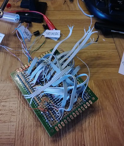
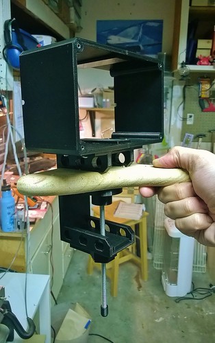
The clamp would be the difficult part, so I started on that. The original plan was to have one large, monolithic 3D printed PLA clamp piece (in yellow above), and then have another printed PLA part – essentially a threaded bolt – that would screw upwards to attach the clamp to the desk. Unfortunately that did not work, because the clamp and bolt had to be printed in different orientations which led to the threads sticking horribly. Because the clamp part took a little over 5 hours to print, I decided I wanted to keep that. So I switched to a #6 steel threaded rod and built an adapter for the clamp. This consisted of a tube that holds a steel nut in the hole of the clamp, sandwiched between two flat parts which are glued (using Super Glue/Cyanoacrylate) in place. Here is the tube with one half of the sandwich (the nut is already embedded in the tube):

And here it is sandwiched and glued into the clamp:

This wheel is what applies pressure to the bottom of the desk. It also has an embedded nut which accepts the threaded rod:

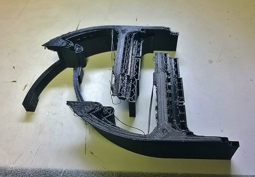
The enclosure body is just two simple flat U-shaped halves glued together with the help of some interior straps. Here is the whole thing (probably around 12 hours of printing in all these parts):

The back of the enclosure would be 1/8″ MDF (sprayed black), while the face plate would be 1/8″ acrylic. The faceplate really was the key to the whole thing. To ensure the profiles for the plugs, switches and buttons were the right size, I first did a trial run on MDF (which costs around 15% compared to acrylic) on the CnC router. Amazingly, I got the sizes right on the first try:

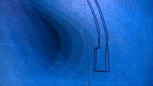
Then came the real cuts – I am not a fan of cutting acrylic on the CnC because the plastic melts and sticks to the router bit, slowly increasing it’s diameter, which leads to inaccurate cuts. Apparently you can get around this by increasing cutting speeds, but I have not yet gotten that to work for me. Another way to solve that would be to buy a laser engraver, but I don’t really want to drop $11k to improve my plastic parts by 10% or so (hardly seems worth it when you put it that way, Dave). Here is the acrylic, still with the blue adhesive protector in place. Actually turned out pretty well:

Once that was done, it was time to design the faceplate art (which labels all the switches, etc). I used OpenSCAD’s projection() function to export the outlines as DXF to Inkscape. Once there, I used the miso font to finish up the art:

I printed the art on my regular printer. Now onto the cutting. This had to be done carefully as the plugs have no bezel, so the edges of the cut would be visible. I used a plain old Exacto knife with a new blade and a lot of patience:

And then add in all the switches and plugs. This is actually the most fun part of the project, because you start to see the interface take shape. You need to be careful not to scratch the acrylic while you do this (which of course I did, but luckily it was a small one):

Instead of using regular screws, I decided to use some Hex-headed 3mm screws, which give a nicer aircraft panel-like look.

You’ll remember that part of the design was two LEDs – one to show if the device is live, and another to show if the digital devices have been inhibited. One of the pictures I saw in the Cockpits book showed indicator lights where the text itself lit up – this was very cool and I decided to replicate that. I 3D printed some housings for the LEDs in natural PLA (which is translucent). This is basically a square cone with the LED at the apex, and a transparency with the caption text at the base. I painted these (except for the base) using silver enamel paint to prevent the light from leaking out of the back of the housing. The entire thing is then attached to the face plate with two screws:

The effect is very cool – while the LED is off, the text is barely legible, and then really lights up in the color of the LED when it is turned on. I will be using this trick in future projects. Here is the entire enclosure coming together:

Next I hot-glued glued the perf to the back plate using some 3D printed standoffs (needed to provide space for the cables beneath). I also, as is my wont, signed the plate with my bunny sketch. You should be aware that when you make your own, this is an optional step:

I decided to done one last round of thorough testing before trying to stuff everything in the enclosure. There are many, many cables in this project:

Here you can see how the LED housing is bolted to the faceplate (top center of the plate):

It’s actually kind of hypnotic trying to see where all the cables connect. You can see why it was important to label everything before we got to this stage:

And here I am testing the mouse functionality – the Atari stick is actually moving the mouse cursor around. Very cool!

I also found a number of bugs around how the switches were labelled relative to what the code actually did (e.g. in the image above, the switches are set to use joystick mode, but the code was actually running in mouse mode). I also found one short circuit which nulled out one of the analog device axes. It always amazes how some bugs manage to hide till the bitter end.

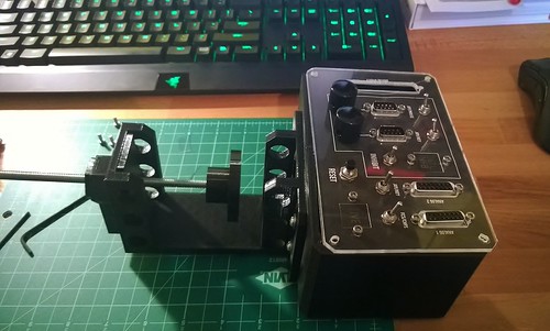
Once everything was tested, it was time to compress it into the enclosure. I had to unplug everything, bolt the back plate (with electronics now attached) to the body, and then re-plug everything in (using tweezers) inside the enclosed space. In order to get everything to fit, I pre-folded some of the ribbon cables so that they collapsed in predictable ways as you squished them in. Then finally I grabbed an Allen key and bolted the faceplate in place:

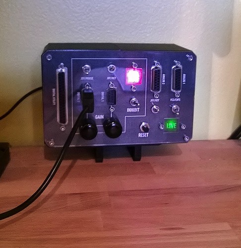
Looks pretty good. Here it is with the desk clamp fitted, and running – notice how the light housings give you nice illuminated text captions (the red LED is brighter than the green):

I did some final testing by setting up Strike Fighters 2 to use the device, plugged in my Thrustmaster Top Gun Platinum stick, jumped in an Israeli Mirage IIIC, and started a huge furball with some Syrian MiG-21s. These two aircraft are very well matched, so there was a lot of stick pulling and grunting, but I got away with two kills before I ran out of ammo and had to run home with bingo fuel. Fantastic! My next round will be to set up Dos Box and use my CH Flightstick Pro to play through the US Navy Fighters Crimea campaign again.

This was a difficult project for sure – large 3D prints, lots of electronics/soldering and firmware coding on top of it all. But being able to use all my old controllers again makes it totally worth it. Total cost in parts was probably around $40 (the only “expensive” piece is the Teensy – the rest is plugs, switches and ribbon cable). If you’d like to make your own, you can get all the STL files as well as the source code for the firmware at Thingiverse.

Read Full Post »

During the 1990s, as flight simulators began to gain popularity with PC gamers, several companies started producing dedicated flight simulation joysticks. One of the cool features of these sticks was the hat switch – a four direction digital mini joystick which was operated by the thumb (usually used to control the view direction). The problem faced in designing such a joystick was how to encode the hat positions given the shortage of pins in the standard 15 pin PC gameport. Essentially, the PC’s gameport has enough pins for two joysticks each with two axes and two buttons (pinout here). Many of these joysticks used three axes already (aileron, elevator and throttle), and all four buttons, which left very little to encode the hat on.

Reading the hat switch of a classic PC joysticks on a modern microprocessor/dev board such as the Teensy USB or Arduino is fairly easy – there are only two major solutions you need to support (depending on the type of stick you want to read).

Thrustmaster FCS method – encode the hat in the fourth axis

The Thrustmaster FCS was the first PC flight stick to include a hat switch.The Thrustmaster Top Gun stick works the same way (it is essentially a re-branded FCS).

Thrustmaster encodes the hat position on the second Y axis (pin 13 on the plug). Moving the hat switch in any direction sets a particular resistance which can be easily read on one of the analog pins of the Teensy USB or Arduino (use analogRead(), which will return a value from 0-1023). The following table defines buckets for each hat position (High and Low are the top and bottom values you can expect the pin 13 analogRead() to be):

CH Products Flightstick Pro method – encode the hat using button chords

The second method of encoding hat switch positions was defined by CH Products for their Flight Stick Pro. It was used by several other sticks, such as the Suncom F-15 SFS, and the Logitech Wingman Extreme.

In this design, moving the hat switch produces multiple button presses simultaneously (i.e. a chord). A side effect of this is that these joysticks do not support pressing more than one of the regular buttons together – doing so produces a ghosting effect where the lowest numbered button wins. For example, if you press buttons 1 and 3 simultaneously, only button 1 registers; and if you press buttons 2, 3 and 4 simultaneously, only button 2 registers. The following table shows the chords that are produced by pressing the hat switch in each direction (the absence of a defined chord means the hat is in the center position). You will need to intercept these chords to use in your project:

Read Full Post »

Older Posts »