Feeds:
Posts
Comments

Archive for the ‘Strike Fighters’ Category

UPDATE (9/1/2014): If you are looking to build a project like this, see my post on the Rabbit Engineering Model I1 device.

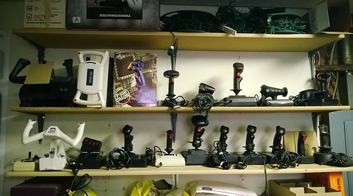
#1stworldproblems – I have a lot of very old joysticks. Too many? No, don’t be silly, no such thing. This hoarding habit is related to my collection of 80s and 90s flight sim paraphernalia in general.

It’s not too bad owning a lot of old flight sim software, because you can just crank up an emulator like DosBox or VICE and enjoy your clunky old untextured polygons. But using your retro flight sim hardware is not quite so easy. You can get an adaptor that allows you to use even the more complex joysticks such as the Thrustmaster FCS, but they have two problems: (1) They only convert PC 15 pin joysticks, and not the Atari/Commodore 9 pin digital sticks and (2) where’s the fun in that? Anyway, what I really wanted was a converter that:

  1. Accepted 9 pin and 15 pin joysticks, including those using the CH Flightstick Pro and Thrustmaster FCS hat switch standards
  2. Accepted two retro joystick simultaneously to allow for joystick/throttle/rudder combos
  3. Converted an analog 15 pin joystick into digital output (for use with emulated 8 bit games)
  4. Converted a digital 9 pin joystick into analog USB joystick (for using digital joysticks with PC sims)
  5. Converted a digital 9 pin joystick into USB mouse input
  6. Accepted arbitrary switches and converted them into joystick buttons for creating new custom input devices (like my previous Strike Fighters 2 radar/armament panel project)

That’s a tall order – this will need to be a microprocessor based project (my first). My first instinct was to use the Arduino Leonardo, which I really like and already have some experience with, but a couple of things put me off – it’s light on memory (2.5k), which limits growth potential for code; it has few digital inputs (20) and although it can be HID-configured as a joystick, it’s not trivial to make it be simultaneously a HID joystick, mouse and keyboard. Plus, it’s physically pretty big. Instead, I went with the Teensy++ 2.0, which uses the AT90USB1286, an 8 bit AVR running at 16MHz. It has 128k of flash, 8k of RAM, 40 digital inputs, 8 analog inputs, and more importantly, it can be easily configured as a Joystick (6 axis, 32 buttons), keyboard and mouse on the same HID device. It’s the size of two postage stamps, and costs $24. And it’s manufactured in the garage of an adorable Portland couple. Perfect.

First thing was to work out the electronics and firmware. For the two analog devices (15 pin joysticks), I would accept one as a full flight stick (i.e. 3 axis plus hat switch plus 4 buttons), and the other would be two axes and four buttons (I only have six output axes after all) – this one would be used as a throttle and/or rudder pedals. This step was fairly easy – get the pinout for a PC joystick, and then remember that PC joysticks use their potentiometers as voltage dividers – this means you need to add a 100kΩ resistor between the Teensy pin and ground:

This is required for each axis. The buttons are a simple case of connecting the Teensy’s digital pin to ground. The hat switches are a bit more complex, because CH Products and Thrustmaster came up with quite different ways of implementing those – more on that in this post. Now for the digital devices (9 pin joysticks), which are very simple – the joystick just connects the input to ground. I decided to expand slightly from the Atari standard by allowing two buttons (like the Commodore Amiga used). Here is the pinout. I also added a 37 pin input to expose all 32 buttons for a custom devices – it surfaces one pin per button, plus one for +5v and one for ground.

Those are the device inputs. In order to implement the various modes for the device, I also needed to add some support inputs:

  1. For each digital device input, a ‘gain’ potentiometer to scale the amount of output on the mouse/joystick.
  2. Because the digital and analog devices share joystick axis outputs, a switch to inhibit the digital devices (otherwise you get interference between them)
  3. A switch to select joystick/keyboard mode output on digital device 1
  4. A switch to select joystick/mouse mode output in digital device 2
  5. A switch to select if analog device 1 uses Thrustmaster FCS or Flightstick Pro hat switch
  6. A switch to select if analog device 2 outputs keyboard or joystick signals
  7. A reset button (needed to reprogram the Teensy).

I also decided to add LEDs to indicate the whole box was live (plugged in), and another to show if the digital devices were inhibited. When you lay all that over the Teensy’s pins, this is what you get:

Note that not all the Teensy’s pins are surfaced on its two side edges – some are in the center of the board. Once all that was locked, I soldered 0.1″ pitch headers on some perf board, and plugged the Teensy in (like a shield). I then got to soldering headers for all the plugs and switches. At this point it is worth pointing out that this is project that used a lot of soldering – somewhere around 400 points. Here I was taking a hand-cramping break:
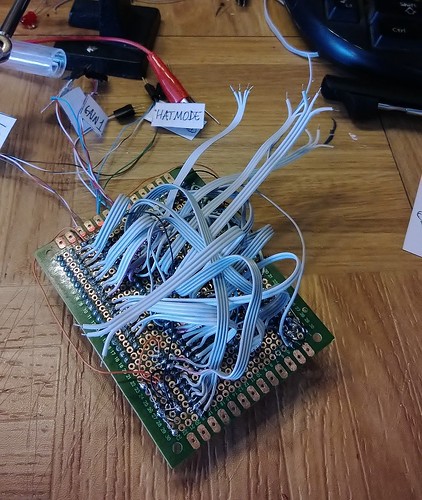
This took several evenings, because I decided to go slow and test each set of connections as I finished them. As there was a lot of cables in a  small space, I would not be able to reach every spot at the end to fix issues.

Notice how I added little labels to connections – this is because I wanted to easily be able to determine which switch connected to which part of the board. When the rat’s nest was all wired up, it would not be possible to visually trace the connections.

As I added physical connections to the board, I updated the firmware to expose the functionality. The code itself was fairly straight forward, and didn’t require a lot of bells and whistles (I did add some code to automatically detect when an analog device was unplugged which I am very chuffed with).

So much for the electronics – now on to the enclosure. I decided to keep the design simple; it would look avionics panel like and hardcore – I took inspiration from the great Cockpits of the Cold War. Last time I tried this, I used a large decal to add the captions to the panel; but after a couple of years, the decal corners have lost their glue, and are peeling slightly. I would avoid that this time by using a sheet of acrylic, with a printed overlay behind it. I also wanted the enclosure to have a clamp so that I could attach it to my desk, and flip switches without it sliding around. Here is the OpenSCAD render of the final design:

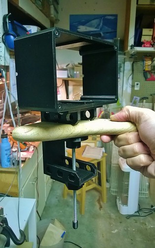
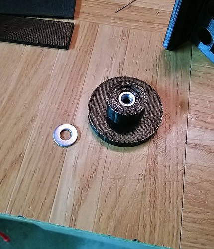
The clamp would be the difficult part, so I started on that. The original plan was to have one large, monolithic 3D printed PLA clamp piece (in yellow above), and then have another printed PLA part – essentially a threaded bolt – that would screw upwards to attach the clamp to the desk. Unfortunately that did not work, because the clamp and bolt had to be printed in different orientations which led to the threads sticking horribly. Because the clamp part took a little over 5 hours to print, I decided I wanted to keep that. So I switched to a #6 steel threaded rod and built an adapter for the clamp. This consisted of a tube that holds a steel nut in the hole of the clamp, sandwiched between two flat parts which are glued (using Super Glue/Cyanoacrylate) in place. Here is the tube with one half of the sandwich (the nut is already embedded in the tube):

And here it is sandwiched and glued into the clamp:

This wheel is what applies pressure to the bottom of the desk. It also has an embedded nut which accepts the threaded rod:
The enclosure body is just two simple flat U-shaped halves glued together with the help of some interior straps. Here is the whole thing (probably around 12 hours of printing in all these parts):

The back of the enclosure would be 1/8″ MDF (sprayed black), while the face plate would be 1/8″ acrylic. The faceplate really was the key to the whole thing. To ensure the profiles for the plugs, switches and buttons were the right size, I first did a trial run on MDF (which costs around 15% compared to acrylic) on the CnC router. Amazingly, I got the sizes right on the first try:

Then came the real cuts – I am not a fan of cutting acrylic on the CnC because the plastic melts and sticks to the router bit, slowly increasing it’s diameter, which leads to inaccurate cuts. Apparently you can get around this by increasing cutting speeds, but I have not yet gotten that to work for me. Another way to solve that would be to buy a laser engraver, but I don’t really want to drop $11k to improve my plastic parts by 10% or so (hardly seems worth it when you put it that way, Dave). Here is the acrylic, still with the blue adhesive protector in place. Actually turned out pretty well:

Once that was done, it was time to design the faceplate art (which labels all the switches, etc). I used OpenSCAD’s projection() function to export the outlines as DXF to Inkscape. Once there, I used the miso font to finish up the art:

I printed the art on my regular printer. Now onto the cutting. This had to be done carefully as the plugs have no bezel, so the edges of the cut would be visible. I used a plain old Exacto knife with a new blade and a lot of patience:

And then add in all the switches and plugs. This is actually the most fun part of the project, because you start to see the interface take shape. You need to be careful not to scratch the acrylic while you do this (which of course I did, but luckily it was a small one):

Instead of using regular screws, I decided to use some Hex-headed 3mm screws, which give a nicer aircraft panel-like look.

You’ll remember that part of the design was two LEDs – one to show if the device is live, and another to show if the digital devices have been inhibited. One of the pictures I saw in the Cockpits book showed indicator lights where the text itself lit up – this was very cool and I decided to replicate that. I 3D printed some housings for the LEDs in natural PLA (which is translucent). This is basically a square cone with the LED at the apex, and a transparency with the caption text at the base. I painted these (except for the base) using silver enamel paint to prevent the light from leaking out of the back of the housing. The entire thing is then attached to the face plate with two screws:

The effect is very cool – while the LED is off, the text is barely legible, and then really lights up in the color of the LED when it is turned on. I will be using this trick in future projects. Here is the entire enclosure coming together:

Next I hot-glued glued the perf to the back plate using some 3D printed standoffs (needed to provide space for the cables beneath). I also, as is my wont, signed the plate with my bunny sketch. You should be aware that when you make your own, this is an optional step:

I decided to done one last round of thorough testing before trying to stuff everything in the enclosure. There are many, many cables in this project:

Here you can see how the LED housing is bolted to the faceplate (top center of the plate):

It’s actually kind of hypnotic trying to see where all the cables connect. You can see why it was important to label everything before we got to this stage:

And here I am testing the mouse functionality – the Atari stick is actually moving the mouse cursor around. Very cool!

I also found a number of bugs around how the switches were labelled relative to what the code actually did (e.g. in the image above, the switches are set to use joystick mode, but the code was actually running in mouse mode). I also found one short circuit which nulled out one of the analog device axes. It always amazes how some bugs manage to hide till the bitter end.

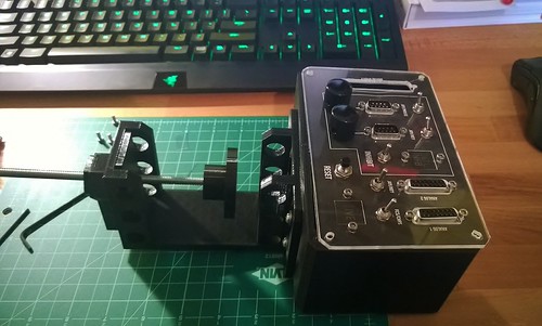
Once everything was tested, it was time to compress it into the enclosure. I had to unplug everything, bolt the back plate (with electronics now attached) to the body, and then re-plug everything in (using tweezers) inside the enclosed space. In order to get everything to fit, I pre-folded some of the ribbon cables so that they collapsed in predictable ways as you squished them in. Then finally I grabbed an Allen key and bolted the faceplate in place:

Looks pretty good. Here it is with the desk clamp fitted, and running – notice how the light housings give you nice illuminated text captions (the red LED is brighter than the green):
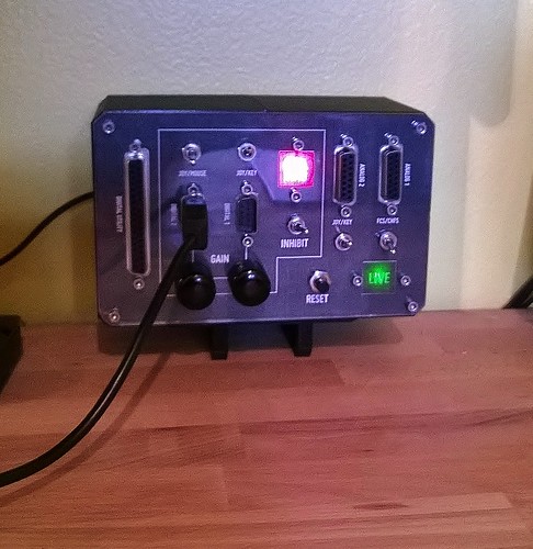
I did some final testing by setting up Strike Fighters 2 to use the device, plugged in my Thrustmaster Top Gun Platinum stick, jumped in an Israeli Mirage IIIC, and started a huge furball with some Syrian MiG-21s. These two aircraft are very well matched, so there was a lot of stick pulling and grunting, but I got away with two kills before I ran out of ammo and had to run home with bingo fuel. Fantastic! My next round will be to set up Dos Box and use my CH Flightstick Pro to play through the US Navy Fighters Crimea campaign again.

This was a difficult project for sure – large 3D prints, lots of electronics/soldering and firmware coding on top of it all. But being able to use all my old controllers again makes it totally worth it. Total cost in parts was probably around $40 (the only “expensive” piece is the Teensy – the rest is plugs, switches and ribbon cable). If you’d like to make your own, you can get all the STL files as well as the source code for the firmware at Thingiverse.
Read Full Post »

Drivers (defining which keypress corresponds to which switch) are now loading from SD. The device bus is scanned on startup, and because each device emits its internal ID, the corresponding driver is located in the SD card and loaded.

Getting SD to work on a Leonardo was a pain – don’t use pins 11, 12 and 13 for SPI as 99% of tutorials tell you – use the pins on the ICSP header, which is on the back edge of the Leonardo, next to the “Made in Italy” caption. The SD library in version 1.0.3 of the SDK works fine without any modifications if you use these pins. More details in this instructibles page.

Read Full Post »

So now I have a matrix keyboard (just 2 rows x 2 columns for testing), with full masking and ghosting protection. There is still a little noise I need to filter out. Here it is being tested with Strike Fighters 2.

This is the prototype. The bottom board holds the CD4021BE (rows) and 74HC595 (columns). The top board has the four switches plus diodes that make up the ‘keys’. The third chip you see is another CD4021BE, which is used to store the device ID.

Read Full Post »

UPDATE (9/1/2014): If you are looking to build a project like this, see my post on the Rabbit Engineering Model I1 device.

So this happened:

That’s an Arduino Leonardo using its keyboard emulation mode to control the landing gear in Strike Fighters 2. At $25, the Leonardo is almost half the price of an iPac2, but being a fully programmable microprocessor, promises to allow hundreds of inputs rather than the couple dozen provided by the iPac.

Read Full Post »

UPDATE (9/1/2014): If you are looking to build a project like this, see my post on the Rabbit Engineering Model I1 device.

Lately I have been on a Strike Fighters 2 binge. SF2 is a great indie combat flight sim, written by Tsuyoshi “TK” Kawahito (a flight sim developer rock star from the 1990s) out of his garage, and sold DRM-free online. The game presents air combat between the 50s and 80s, and is in the tradition of the old ‘survey sims’ of the 1980s and 90s. It has a solid user community, with lots of free add-ons available.

As with a lot of older flight sims, there are a lot of keyboard commands. Frankly, looking at your keyboard while you fly breaks presence for me. This is the reason why people buy HOTAS controllers, after all. But of course, you can’t get all your controls into a HOTAS setup. For commercial flight simulators (like FSX), there are many dedicated controllers like Saitek‘s Multi Panel or Radio Panel, but there is really nothing comparable for combat sims.

So time to build a set of custom controllers for SF2. I realized that part of the coolness of the Saitek controllers was that they look like the real thing. So I did a little research into combat aircraft panels from that era. Here are two representative ones:

This is part of the defense panel from an F-4. Black panel, white line breaking up the controls into groups.

This is part of the input panel from an A-6’s DIANE computer. Again, black with white sans-serif text, and again big, chunky controls (to be usable while wearing flight gloves). In general, everything is kind of lumped together, but grouped using text and likes on the panel. So this was the look I would try to reproduce in my panel. On top of that, I wanted to keep the entire project cost under $100 (the cost of a typical Saitek panel), and it had to be easy to setup/teardown on my desk. Finally, it had to be plug-and-play; no messing with software, loading profiles or calibrating anything. It would use the IPac2 Distribution box to interface to the PC.

I decided that the controls I would build would be an armament panel, radar control panel, and some miscellaneous controls (gear, flaps, etc). The idea was to cover as many of the common aircraft functions as possible between HOTAS and these new panels; sim-only controls (such as time compress, the map and radio controls) could remain on the keyboard.

The project: Custom controllers for Strike Fighters 2

Because this project was intended to have a clean look, planning was more important than ever. I began thinking about how many game functions to map onto the 32 available inputs, and on what type of physical control to surface them (rotaries, buttons or toggles).

click for more sizes

Once that was cleared and I had the count of how many of each count I needed, I bought them at Jameco. I then carefully measure each one to plan the layout on the 5″ enclosures:

click for more sizes

Picking your parts early is important so that you can measure and lay things out correctly.I began by choosing a good box – ABS plastic, basically 5″x5″, which I found at Skycraft Parts & Surplus. I also used three types of control (bought them all at Mouser):

In order to plan the layout, I would need something more accurate than my chicken scratchings. I used Scribus (an open source page layout editor) to do an accurate plan which I could print at 1:1 scale. Because the plan is digital, you can play with many arrangements and think about how things will work together without risking any materials or parts. In the end I finished with this arrangement:

click for more sizes

A huge advantage of using page layout software like Scribus is that you can print out the layout and use it directly as a template to drill with etc. Once the layout was finalized, it was time to create a ‘decal ready’ version:

Download my Scribus 1.3 file. Notice how a little circle was left to indicate where to drill. Incidentally, the font I used is Miso, which is free.

This version was then printed onto decal inkjet paper, overlaid with a transparent, self-adhesive film to protect it from spills etc, and then stuck directly onto the enclosures. Here they are ready to drill:

Now we drill. The different controls required different size holes (which are measured from the electrical parts directly). The most interesting were the buttons, which needed a half inch hole (12.7mm). To do this in plastic, you need to use a spade bit, which is a mean looking implement:

When it is done with the hole, the spade bit leaves behind this amusing looking wormy thing:

Although my bits were new and sharp, they dis leave a slightly ragged edge on the decal. This is not really a problem, as each control has some form of lip which covers this up later.

Now that all the holes are drilled, you can attach the controls themselves, in preparation for soldering.

Attaching the controls is fairly straight forward – screw them into place. Be careful in tightening them though, as most buttons/pots have either plastic or aluminium threading, which will pop easily under a lot of force (and then you are stuck with a button/pot you can’t use). Once they are all in, solder all the common poles together in series, and then put one cable to each control. Buttons get single cable, but the rotary switches and toggles get two apiece. I used a ribbon cable from a (very) old 3″ floppy disk. These cables are compact and solder quite well, so work nicely for this kind of project. Here is one completed:

Notice that the back of the box (black bit above) has had a rectangular slot cut out (with Dremel) to allow the ribbon cable to pass through. I then capped the cable off with a DB9 plug, so that I could plug into my IPac 2 distribution box. Due to the number of controls in a box, each of them had two DB9s wired up. To finish off, I added two strips of self-adhesive non-slip rubber tape to the bottom of each box (I had this left over form an automotive project). This prevents it from moving around the table as you use them, and also allows the ribbon cables to pass under the controls. Here they are ready to test:

Click for more sizes

Now for the setup. I plugged them into the distribution box. Quite pluggy:

I then fired up the IPac programming utility and set it up. Because the IPac 2 has flash memory, it keeps its programming even without power. That means I don’t have to re-program each time – just plug and fly.

This is how it is positioned – between the throttle and keyboard. Notice that The ribbon cables of the box closer the the desk edge pass under the other box, and up to the distribution box. This is another advantage of using ribbon cables instead of bundles.

Testing went very well – after entering the new key bindings into Strike Fighters 2, I was off blowing things up. The chunky buttons and switches really fit with the level of technology presented in teh game. Having the rotary switches especially makes for a very nice experience for things like radar mode and range. This project cost about $40 for the control panels (the rotary switches are a little expensive – you can save probably $15 by using toggles instead), and about $50 for the distribution box (which includes the price of the IPac). Well worth it, especially given there is nothing like it to buy off the shelf. And of course, you can use this for any sim that takes keyboard inputs (including the old classics for DOS, if you are running them inside DosBox in Windows).

click for more sizes

Read Full Post »

Third Wire, makers of the Strike Fighters/Wings over and Strike Fighters 2 series, are having a 30% sale on everything in their inventory – that means a complete, modern combat flight sim for $20. DRM free, direct download from their site. Remember: TK and his tiny band of brothers are indie developers who need sales to buy their dinners! Support them!

Go there right now!

Need some motivation? Head over to CombatAce and see the sheer volume of free add-ons you can get – including Operation Desert Storm for Wings over Europe

Need more? Here is a nice movie of Strike Fighters 2: Isreal

And some screenshots from various of their titles (click for full size):

Click for full size

Click for full size

Click for full size

add to del.icio.us : Add to Blinkslist : add to furl : Digg it : add to ma.gnolia : Stumble It! : seed the vine : : : post to facebook

Read Full Post »

UPDATE1: You can now download the mod from a mirror as a single large file (no login required).

During the 80s and 90s, Bill Gunston wrote a bunch of really cool books on military hardware. These were gung-ho, geek friendly books that focused on the numbers (number of missiles, rate of climb, etc), and completely left out all the bad stuff about war. Together with some really good art, they presented a Tom Clancy view of war, long before Tom Clancy started writing. And of course, being British, Gunston gave everything a nicely off-center view – British was always best, and non-American subjects often got center stage in his books.

One of Bill Gunston’s classic books. No accident that an RAF Tornado is on the cover; for Bill, British was always best (click for more sizes)

Combat flight sims have always had the opposite slant – most major developers were American, and with a few notable exceptions (DI’s Tornado and Spectrum Holobyte’s MiG 29) the same list of flyable planes came by over and over again – F14s. F15s, F16s, etc, etc, etc. No chance to fly Hunters, Jaguars, Su-9s, MiG23s or any of the other major players in the Cold War. What a lot of us wanted was the “Bill Gunston flight sim”. The closest we came was Fighters Anthology (a re-release of the excellent U.S. Navy Fighters, published under the Jane’s label), which was a really good game with a good range of planes to fly, but was sadly a little outdated by the time it hit the streets.

Even the Operation Desert Storm menu is a tribute to U.S. Navy Fighters. This mod knows its pedigree.

Enter TK – Tsuyoshi Kawahito. A 1990’s Flight Sim superstar developer behind some of the best titles of the last great wave of flight simulation – European Air War , Jane’s F-15, Longbow and Longbow 2. After Microprose went bust and Jane’s lost interest in PC gaming, TK disappeared for a couple of years. In 2002, he suddenly emerged with the PC game development equivalent of a garage band, Thirdwire Productions. His first release, Strike Fighters: Project 1, made it obviously apparent that TK had not lost his knack. But unlike the old days where content was dictated by the publisher, this time TK was making a flightsim geek’s game – set in the late 60’s and featuring all those great underdog aircraft such as  the A-4 and F-100. TK released new games based on improvements on the engines, all with niche settings (Vietnam, the Arab-Israeli wars).

When’s the last time a flight sim let you fly a MiG-25? ODS lets you indulge in all you most secret aviation fantasies

The greatest of all was Wings over Europe (WoE), set in the late 70’s / early 80’s in central Europe. If the phrase “Fulda Gap” means anything to you, then this was a game you need to play. The aircraft featured were some of the canon (A-10, F-15), but also some for the connoisseur – The Hunter F.Mk 6, Harrier Gr. Mk 1, F-105, Luftwaffe F-4Fs, and others (if you have heard rumors that Wings over Europe doesn’t run on Vista/Windows 7, I don’t think they’re true – I have been running it under both for years).

F-15E lays down – WoE has a solid, fast graphics engine packed with nifty tricks like self-shadowing aircraft and Hollywood style special effects

Now what really makes Wings over Europe a flight sim geek’s game is the open architecture. Everything is configurable in this game. You can add aircraft, tanks, weapons, terrains, modify the UI, you name it. All the tools and docs are released by TK, and there is a huge fan community creating really good stuff – head over to Combat Ace for the best centralized forums/file library. Hiding in that huge library is a true gem – Operation Desert Storm, a total conversion mod. Wings over Europe with the Operation Desert Storm mod is the finest combat flight sim experience you can have on a PC. It is Bill Gunston, the flight sim.

RAF Tornado – ODS lets you pick skins for various famous nose art variations, such as “MiG Eater”

The ODS team take over a whole install of WoE. You have access to a huge number of flyable planes from all the nations that took part in the war (including Canada, Italy, Kuwait and Saudi Arabia), era appropriate weapons, and a detailed map of Iraq and neighboring countries (including aircraft carriers in the Gulf). You can also fly a huge number of campaigns for all the major combatants on the coalition side (including RAF Jaguar squadrons, Italian Air Force Tornado squadrons, US Navy A-6E squadrons, and even the USAF F-117A squadron).

All kinds of flying are available – from stealthy to brute force

The replay value on this mod is very high. You have about 20 variations on the campaign if you include all the different aircraft and nationalities. For instance, if you choose an attack squadron from the US Navy, you will mostly get carrier based missions. Choose an RAF Jaguar squadron and you get a lot of CAS and SEAD missions; but with an RAF Tornado squadron, you probably fly from a different base and get mostly strike and interdiction missions.

This mod gives you land based and carrier based missions

The aircraft themselves fly quite differently, so there is a lot of variation. Although the basic controls of the aircraft are the same, the virtual cockpits are fairly different, so if you turn the overlay off, you need a bit of familiarization time with each one before you can stay in the air for longer than 15 minutes. The flight models are also quite different. So flying missions in the F-117 you need to think ahead for threats, whereas if you are in an F-15E, you have a lot more acceleration and maneuverability to get you out of trouble.

The virtual cockpits of most aircraft are detailed enough to present a nice challenge. Nice detail of the WoE engine – the rear view mirrors work.

Choosing the aircraft or squadron also dictates to some extent the types of missions you get (as is the norm in this sort of game). ODS gives you the full gamut. CAP, SEAD, CAS, strike, interdiction, fighter sweep, war at sea, and even reconnaissance (which is almost never included in this sort of game). There are also some nice set-piece missions. For instance, the battle of Khafji is nicely done, with columns of tanks firing against each other, SAMs hiding among the resort town buildings, and a veritable wall of AAA over the area. And because so many units were involved in that battle, you have the opportunity to fly that battle in a variety of aircraft (USMC Harriers, USAF A-10s, etc).

Air defenses are heavy in ODS – many of your flights will end with you swinging in the silk

In terms of difficulty, the game is quite well balanced. Air combat is not too hard, provided you can get off the first shot (heaven help you if you are in an F-14 versus a MiG-29 and you don’t manage to get the first shot off…). There is a good variety in skills of the enemy pilots, but getting caught in a one-0versus-many fight is always a bad idea. The air defenses are hard – due to their sheer numbers (especially AAA) getting in to some targets can be an interesting problem.

Modern air defenses versus old technology means often ditching your weapons and turning tail

The missile speeds are modeled accurately, so the amount of time between someone calling a SAM launch, you seeing the missile, realize that it is guiding on you, and then hopefully pulling an effective evasive maneuver  is just a few seconds. And of course, getting your weapons on target is always a challenege. Some of the more modern aircraft (Tornado, F-15E, Jaguar) have advanced ground attack avionics on the HUD, but the older ones (like the A-4 and F-111) require old fashioned dive bombing with the correct bomb sight mil setting.

KARI, Iraq’s integrated air defense network, presents a challenge on almost every mission

If you download ODS and just stick to flying the usual suspects (F/A-18, F-15, F-16, etc), then you are missing most of what makes this mod magical. Take a shot at flying with the Free Kuwaiti air force, and see what it’s like to take on the best 1980s Soviet air defenses with essentially a 1960’s aircraft. Try a single mission with an S-3 Viking, bombing Iraqui patrol boats with almost no bombing equipment. Go up with an Iraqi Mirage F.1 strike package and try to punch through the impenetrable CAP screens put up by the coalition. There are many, many different things to do in this mod.

This mod gives you a chance to try the unusual. Campaigns are more limited, but single missions have tons of variety.

Do I have anything bad to say about this mod? Let’s see – it’s free, it collects some of the best mods for WoE into a single pack, it’s set in a truly interesting period in air combat history, and it gives us the Bill Gunston sim we’ve all been waiting for for years. So no, nothing bad to say. Just go get it:

add to del.icio.us : Add to Blinkslist : add to furl : Digg it : add to ma.gnolia : Stumble It! : seed the vine : : : post to facebook

Read Full Post »