This story begins with a simple email about rotary encoders, and ends with me shipping my first paid commission.

It’s a big personal milestone, but really not as a big a deal as you might think in terms of just getting it done. The device I designed and delivered was the Rabbit Engineering Model I1, an interface module that lets flight sim cockpit builders (like my customer), home arcade cabinet builders, and anyone who wants to build a custom controller to connect a variety of buttons, switches, potentiometers, and rotary encoders to their computer by USB. You can get an overview on the product page, and order one for yourself.
By the way, if you get the chance to make a project for someone who has a real problem that you can solve for them, I strongly recommend you do it – this has easily been the most satisfying spare-time project I have worked on.
In early August, I got an email from Mr. G (he has a real name, but let’s keep it anonymous) asking about the rotary switches I used in my custom SF2 controller. He asked simply if I knew of a place that sold them cheaply. After a couple of mails, I suggested he use rotary encoders together with a microcontroller like the TeensyUSB. Alas, Mr. G did not have the skills to pull that off. So I thought, hey, why not help a fellow flight simmer out and build it for him? I offered to do it for the cost of parts plus a small markup. He accepted. We had a commissioned job!
I had already had experience on similar projects and experiments such as the FSX MCP panel, the iPac distribution box, the SF2 controller, the Arduino Leonardo keyboard experiments, and the Multijoy_retro; so I was confident I could pull it off in a month or so.
When doing any kind of engineering project it’s important to set a clear spec (specification) by working with the customer – so we had a long exchange about exactly what the machine would do, I offered some options (with the relative costs), and Mr G. settled on what solved his problem and fit his budget. A simple agreement email locked us both in (I would deliver by end of August, and he would pay the agreed amount), and the three week clock began to tick down.

Essentially, it would be an interface device that would have as many as 42 buttons, switches, rotary encoders or potentiometers connected and converted to key presses, joystick buttons and/or joystick axis events. It would connect to the host by USB without drivers, and the configuration would be programmable by a config file on an SD card. Here is the final spec we agreed upon.
- 42 configurable inputs, all can be used as binary IO, each using one of two modes:
Push-Hold – the event occurs as long as the button is held down (for push buttons).
Push-Nohold – the event occurs only once, regardless of push duration (for single events coming out of toggle switches)
- All can be used to sense 21 rotary encoders (2 inputs needed per rotary). Clockwise rotation sends one event, Counterclockwise rotation sends a different event
- 6 can be configured as analog inputs, sensing a 10K potentiometer (linear or logarithmic).
- Inputs can generate any of the following events:
Key press/release – single key, or with one modifier key (shift, ctrl, alt)
Joystick button press (one of 32 buttons)
Analog inputs can be mapped to one of 6 joystick axes
- Configuration of the inputs is done by modifying a text file in an SD card which is read when the device is plugged into the USB port.
I really tried to convince him on an option to have expansion cards that would add more inputs using shift registers, because it was a feature I wanted to work on; but it broke his budget. In the end, you build for the customer and not yourself, so his decision stood.
Now the design phase – I had already played around with rotary encoders and the TeensyUSB, but only using interrupts. To satisfy the spec I would need more than the handful of interrupts that the Teensy provides, so I began to experiment with polling modes. This was kind of a risky/dumb move on my part, because if I failed to figure it out I would have had to break the spec/cancel the project/upset the customer, but believe me, that fact was very motivating. After a couple of evenings slaving over a hot C++ compiler, I got that working; turn clockwise and you get one input set, turn counterclockwise and get another, with minimal side effects (turn the rotary too fast and you miss steps, which is a bug the Saitek Pro Flight Multi Panel also has!). The other interesting feature, PushNoHold (holding down a button triggers only one input event) was easily done using the standard Arduino Bounce library.

The next “interesting” part in terms of code was SD card reading, which really should not have been hard, but gave quite a few hassles. Ultimately it was all related to the type of SD card – I needed to use an SDHC type rather than the SD types I was assuming I could use. Remember kids, try different disk formats if you’re having disk reading issues.
The big technology choice for this project was the microprocessor to use. I am a big fan of the TeensyUSB line, and I already have experience with it, so I knew it would be the one. I chose the Teensy 2++ in the end because of its large number of input pins and RAM; To satisfy the configurability requirement in the spec, I would need storage per input and 2KB would not be enough.

One painful (hardware) bug I hit was around pin 6 on the Teensy 2++. This is connected to the LED, and so behaves differently from the other pins. In order to turn this into a normal input, I had to add a pull-down resistor, and have the input connect to 5+ rather than to ground like the other pins. Rather than try to reconfigure a big part of the project, I decided to document the strange behavior in the manual (a trick I learned from Clive Sinclair and his scientific calculator).
Writing the code was fairly straightforward, but my days as a C# programmer have left me soft and flabby in terms of pointer handling, so I got slapped around a bit by C++. One fine evening, at about 5am, I finally got all the code running and tested. This project actually has the most code of any I have done (mostly around the config file parsing).

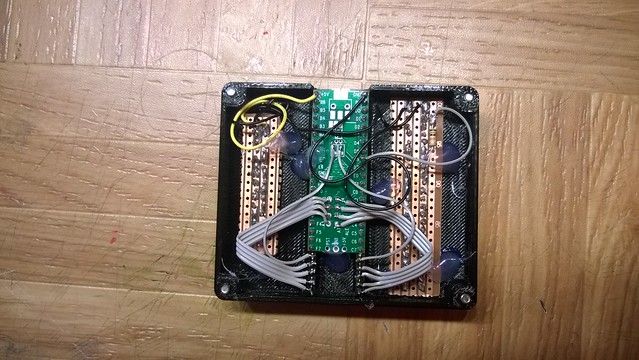
Time to move onto the physical design. There were two aspects to this: Provide an interface to the input pins, ground plane, and +5 supply (needed for potentiometers) in a way that would make for simple integration of the Model I1 into the electronics of the customer’s project; and then a protective shell and means to physically attach it into the customer’s project (by gluing, bolting, or whatever).
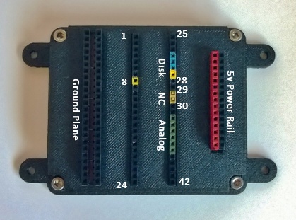
The interface was the most important part – I decided to simplify things by having three clusters of connectors: The input pins (two long headers), a ground plane (a pair of headers with way too many pins), and a power rail with +5 and ground right next to each other. This makes adding input devices simple – just add some male 0.1″ headers and away you go.

And here it is in the shell. The tolerances were tighter than in previous projects, because I wanted to be as compact as possible (the bigger this device, the bigger the customer’s enclosure would have to be). Why yes, that is our old friend hot glue there.
The manual (more on that below) explains how to wire and connect each type of input device (potentiometer, button, etc). I used color coding on the headers to ensure that connecting was as error-free as possible.

Here it is painted (the white numbers are not on the device – this is actually a screen grab from the manual):
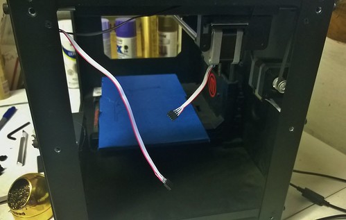
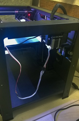
Then came the testing. Testing is not my favorite part of any build, but on this project which would be going out into the wide world and would be hard to fix once deployed, I took some extra time and built a little test rig with the various types of input devices attached. Well, “test rig” is a kind term, it’s a chunk of MDF with some holes. Still, it did the job OK.

Then I tested every type of input on every pin. Good times. Grudgingly, I admit it was worth it because I found two software bugs and one short circuit.

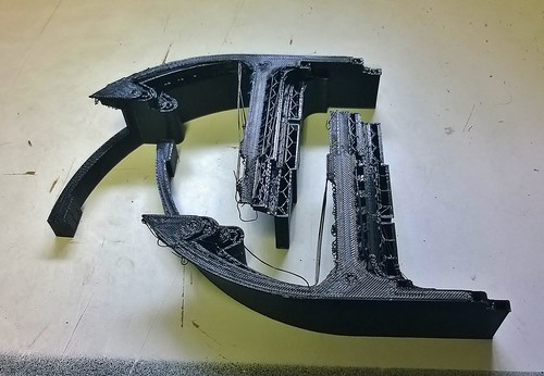
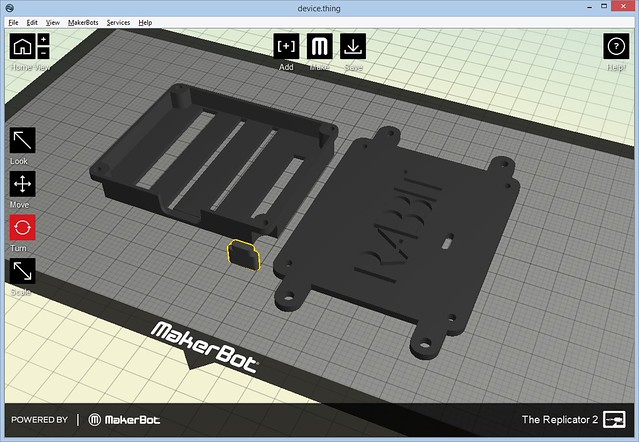
The plastic shell was designed in OpenSCAD and 3D printed. As usual, it began with a sketch (which I made in Las Vegas while there for Black Hat 2014/Defcon 22 – always carry a sketch book with you!).
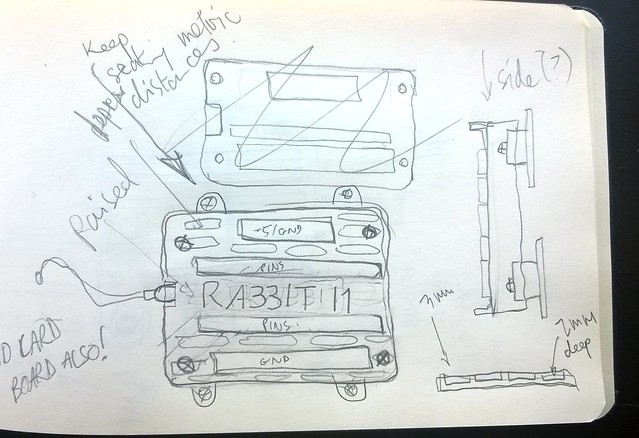
I wanted to give it a designed look, but at the same time this would live inside a beige box one day, so spending too much time was not necessary. It is essentially a flat box with mounting holes, but I used hex bolts instead of screws to give it a little interest.

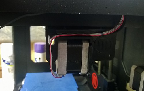
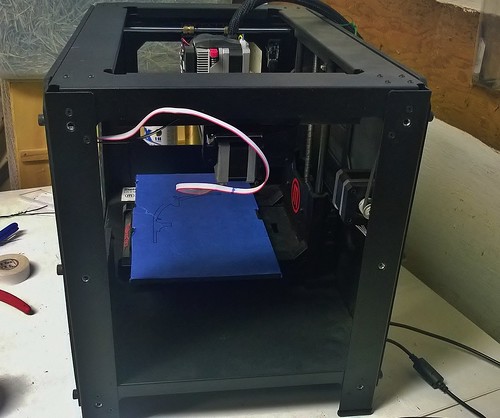
Then the printing (I think total print time was around three hours):
And presto! We have a shell:

I embossed the Rabbit logo on the back, as there was a huge expanse of plastic.

I also printed a matching shell for the SD card disk drive.

For physically mounting the Model I1 to a project, there are two options – you can bolt it in using the bolt holes in the shell, or you can screw in the provided “gluing feet” – you then glue the feet to your project. The idea is that you don’t want to glue the device itself to your project, because if you need to move/remove, the force could damage it. So instead you can just unscrew the device from its feet, and then grunt and pull at the feet all you need without risking the delicate electronics (a trick I developed for the Multijoy_retro).

Then came the writing – this beast would need a detailed manual, because I had to document not only how to connect input devices, but also the file format for the configuration file (which is fairly complex due to all the options you can have). If you thought testing was bad, then writing is the worst, but a well documented product really makes a huge difference – not only does it give an impression of quality and thoroughness, but it saves you a lot of time and energy from all the customer questions/emails you have avoided.

Once all that was done, it was time for the finishing touch – update the Rabbit Engineering site with the product information, and then build a nice packaging experience. When you are building for a paying customer, their experience of their product starts from the very moment they open the box, so that deserves some design and attention also. Sadly, there is no cardboard 3D printer, so a lot of Xacto and sticky tape action followed.

The manual goes on top. This is essentially the first contact the customer has with the device they just bought, so you want to create a “Woah, cool!” reaction.

Then , when they remove the manual, they see all the parts neatly laid out in the box.

Pack all that into into a shipping box, and off it goes to its new home in the wilds of North Carolina. Apparently it’s wild there, I’ve never been, so I will take their word for it.

In the end I was able to get the project done just three days short of the promised date. From conception to shipping was just over 20 days – this was possible mostly because I had already solved all of the underlying problems before I began. If you need a Model I1 for your own project, you can order one up from our online store.
 This is the 2001N model – the first to have a real keyboard and boosted RAM (up from 8KB in the original 2001 model). Available in the Rabbit Engineering online store.